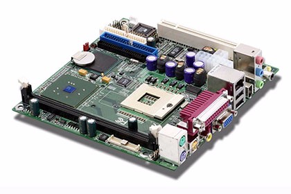
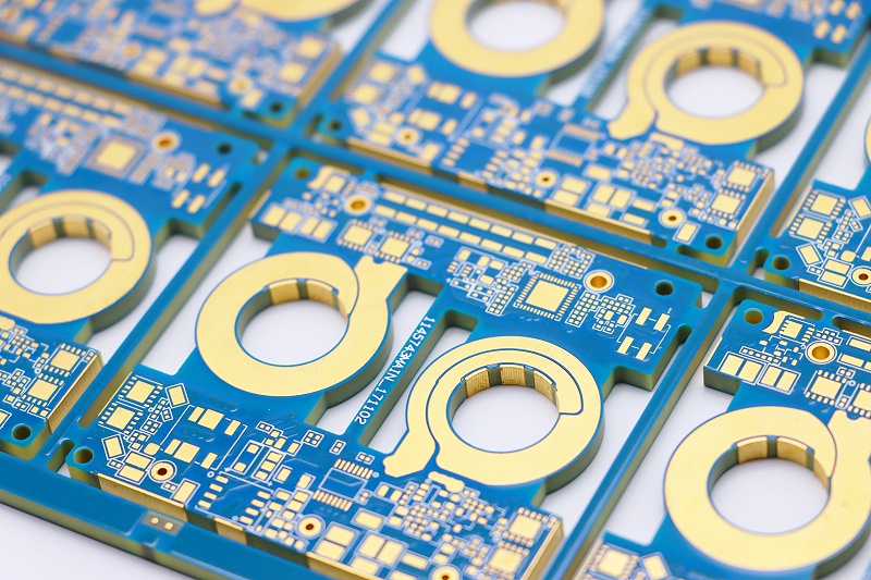
What are the parameters of the circuit board?
PCB circuit board parameters
1. ∑ Dielectric constant (DK value): Usually represents the ability of a certain material to store electrical energy. The smaller the ∑ value, the smaller the ability to store electrical energy and the faster the transmission speed.
2. TG (glass transition temperature): When the temperature rises to a certain area, the substrate will change from “glass state” to “rubber state”. The temperature point at this time is called the glass transition temperature (Tg) of the board. Tg is the maximum temperature (℃) at which the substrate remains “rigid”.
3. CTI (Current Tracking Resistance Index): Indicates the quality of insulation. The larger the CTI value, the better the insulation.
4. TD (thermal decomposition temperature): an important indicator to measure the heat resistance of the plate.
5. CTE (Z-axis) – (Z-axis thermal expansion coefficient): a performance index that reflects the decomposition of thermal expansion of the plate. The smaller the CTE value, the better the performance of the plate.
PCB board knowledge and standards
At present, there are many classification methods for copper-clad laminates that are widely used in our country. Generally, according to the reinforcing materials of the board, it can be divided into five categories: paper base, glass fiber cloth base, composite base (CEM series), laminated multi-layer board base and special material base (ceramic, metal core base, etc.). If classified according to the resin adhesive used in the board, common paper-based CCI include: phenolic resin (XPc, XxxPC, FR-1, FR-2, etc.), epoxy resin (FE-3), polyester Resin and other types. Common fiberglass cloth-based CCLs include epoxy resin (FR-4, FR-5), which is currently the most widely used fiberglass cloth-based type.
There are also other special resins (using glass fiber cloth, polyamide fiber, non-woven fabric, etc. as additional materials): bismaleimide-modified triazine resin (BT), polyimide resin (PI) , diphenylene ether resin (PPO), maleic anhydride imine-styrene resin (MS), polycyanate resin, polyolefin resin, etc. According to the flame retardant performance of CCL, it can be divided into two types of boards: flame retardant type (UL94-VO, UL94-V1 level) and non-flame retardant type (UL94-HB level). In the past year or two, as countries have paid more and more attention to environmental protection issues, a new type of CCL that does not contain bromine has been divided into flame-retardant CCL, which is generally called “green flame-retardant CCL” . With the rapid development of electronic product technology, the requirements for CCL have become higher.
Therefore, from the performance classification of CCL, it is divided into general performance CCL, low dielectric constant CCL, high heat resistance CCL (generally the L of the board is above 150°C), and low thermal expansion coefficient CCL (generally used on packaging substrates). ) and other types. With the development and continuous progress of electronic technology, new requirements are constantly put forward for PCB substrate materials, thus promoting the continuous development of copper-clad laminate standards. Currently, the main standards for substrate materials are as follows:
① National standards: my country’s national standards for substrate materials include GB/T4721-47221992 and GB4723-4725-1992. The copper-clad laminate standard in Taiwan is the CNS standard, which was formulated based on the Japanese JIs standard in 1983. release.
② International standards: Japanese JIS standards, American ASTM, NEMA, MIL, IPc, ANSI, UL standards, British Bs standards, German DIN, VDE standards, French NFC, UTE standards, Canadian CSA standards, Australian AS standards, FOCT standards of the former Soviet Union, international IEC standards, etc.; common and commonly used suppliers of PCB design materials include: Shengyi\Kingboard\International, etc.
PCB boards are divided according to brand quality level from bottom to top as follows: 94HB-94VO-CEM-1-CEM-3-FR-4
Its specific parameters and uses are as follows:
94HB: Ordinary cardboard, not fireproof (the lowest grade material, die-punched, cannot be used as a power board)
94V0: Flame retardant cardboard (die punching)
22F: Single-sided semi-fiberglass board (die punching)
CEM-1: Single-sided fiberglass board (must be computer drilled, not punched)
CEM-3: Double-sided semi-glass fiber board (except for double-sided cardboard, it is the lowest-end material for double-sided panels. Simple double-sided panels can use this material, which is 5~10 yuan/square meter cheaper than FR-4)
FR-4: Double-sided fiberglass board
1. The classification of flame retardant properties can be divided into four types: 94VO-V-1 -V-2 -94HB
2. Pre-cured sheet: 1080=0.0712mm, 2116=0.1143mm, 7628=0.1778mm
3. FR4 CEM-3 both represent boards, fr4 is fiberglass board, and cem3 is composite substrate
4. Halogen-free refers to substrates that do not contain halogens (fluorine, bromine, iodine and other elements), because bromine produces toxic gases when burned.
5. Tg is the glass transition temperature, that is, the melting point.
6. The circuit board must be flame-resistant and cannot burn at a certain temperature, but can only soften. The temperature point at this time is called the glass transition temperature (Tg point). This value is related to the dimensional durability of the PCB board.
What is high Tg? PCB circuit board and the advantages of using high Tg PCB
High Tg refers to high heat resistance. When the temperature of a high Tg pcb circuit board rises to a certain threshold, the substrate will change from “glass state” to “rubber state”. The temperature at this time is called the board The glass transition temperature (Tg). Equivalently, Tg is the maximum temperature (°C) at which the base material remains rigid. That is, ordinary PCB circuit board substrate materials continue to soften, deform, melt, etc. under high temperatures. At the same time, they also show a sharp decline in mechanical and electrical properties, which affects the service life of the product. Usually Tg boards is above 130°C, high Tg is usually greater than 170°C, and medium Tg is about greater than 150°C; PCB circuit boards with Tg ≥ 170°C are usually called high Tg PCB; the Tg of the substrate is increased, and the heat resistance and moisture resistance of the circuit board are improved , chemical resistance, resistance and stability and other characteristics will be improved and improved. The higher the TG value, the better the temperature resistance of the board. Especially in lead-free processes, there are many high Tg applications.
With the rapid development of the electronics industry, especially electronic products represented by computers, which are developing towards high functionality and high multi-layering, higher heat resistance of PCB circuit board substrate materials is required as a prerequisite. The emergence and development of high-density mounting technologies represented by SMT and CMT have made PCB circuit boards increasingly inseparable from the support of high heat resistance of the substrate in terms of small aperture, fine wiring, and thinness.
Therefore, the difference between ordinary FR-4 and high Tg is: at high temperatures, especially when heated after absorbing moisture, the mechanical strength, dimensional stability, adhesion, water absorption, thermal decomposition, and thermal expansion of the material There are certain differences in different situations. High Tg products are obviously much better than ordinary PCB circuit board substrate materials.
What are the important parameters of high-frequency PCB?
The dielectric constant (Dk) of the high-frequency circuit board substrate must be small and stable. Generally speaking, the smaller the better. The signal transmission rate is inversely proportional to the square root of the material’s dielectric constant. A high dielectric constant can easily cause signal transmission delays. .
The dielectric loss (Df) of high-frequency circuit board substrate materials must be small, which mainly affects the quality of signal transmission. The smaller the dielectric loss, the smaller the signal loss.
The impedance of high-frequency circuit boards actually refers to the parameters of resistance and reactance. Since PCB circuits must consider the insertion and installation of electronic components, and consider issues such as conductive performance and signal transmission performance after plugging, the lower the impedance, the better. .
The base material of high-frequency circuit boards should have low water absorption. High water absorption will cause dielectric constant and dielectric loss when it gets wet.
In order to meet the signal integrity requirements of different applications, PCB not only needs to test S parameters and TDR impedance, but also needs to analyze the physical properties of the material itself, dielectric constant and dielectric loss. An accurate dielectric constant can not only achieve effective design, but also make simulation and product real test results more consistent, improve the efficiency of design and development, and is of great significance to PCB material suppliers, including PCB production developers.


