Causes and solutions of crosstalk on PCB
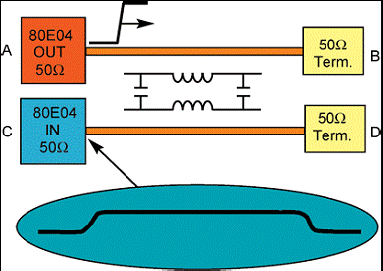
PCB (Printed Circuit Board) is a very important component of electronic products. It connects various electronic components and provides electrical connections and mechanical support. Crosstalk is a common problem during PCB design and manufacturing that can negatively impact circuit performance. This article will detail the causes of crosstalk on PCBs and provide some solutions.
1. Causes of crosstalk
1. Electromagnetic interference (EMI)
Electronic equipment generates electromagnetic radiation during operation. Changes in current and voltage on signal lines will generate magnetic fields, causing changes in charge and current on nearby lines, thus causing crosstalk. Electromagnetic interference mainly originates from high-frequency signals, ground return flow and power supply return flow.
2. Signal Integrity (SI)
Signal integrity refers to the ability of a signal to maintain stability and accuracy while traveling through a circuit. When signals are transmitted in PCBs, they are affected by factors such as impedance mismatch, signal coupling, and backflow, which can lead to signal distortion and crosstalk.
3. Power supply noise
Power supply noise refers to changes in voltage and current caused by power supply voltage fluctuations, power line impedance mismatches, and other electrical factors. Power supply noise can couple to other lines through the power lines, causing crosstalk.
4. Asynchronous clock system
When there are multiple clock sources on the PCB, since the frequency and phase of each clock source may be different, mutual interference between signals will occur, resulting in crosstalk.
2. Solution
1. Electromagnetic shielding
In order to reduce electromagnetic radiation and electromagnetic interference, electromagnetic shielding measures can be used on the PCB. For example, add ground wires, power wires, or electromagnetic shields next to high-frequency lines to reduce the level of interference.
2. Reasonable wiring and layout
Proper wiring and layout can reduce signal coupling and crosstalk. First, the length and area of signal lines should be minimized to avoid intersection and overlap of signal lines. Secondly, avoid placing high-frequency and low-frequency lines on the same level, as well as placing signal lines and power lines in adjacent locations.
3. Impedance matching
To ensure signal integrity, impedance matching should be implemented in the PCB design. Add an impedance matching resistor at the end of the signal line to ensure normal signal transmission. In addition, PCB software simulation tools can be used to optimize impedance matching.
4. Optimize power supply design
Optimizing the power supply design can reduce the impact of power supply noise on other lines. First, the length and impedance of the power cord should be minimized. Secondly, components such as power filter capacitors, power regulators, and power isolators should be added to the PCB to reduce power supply noise.
5. Synchronized clock system
In order to avoid the crosstalk problem of asynchronous clock systems, synchronous clock systems can be used. The synchronous clock system can ensure the consistency of the frequency and phase of each clock source and reduce crosstalk through synchronous control of clock signals.
The above is a detailed introduction to the causes and solutions of crosstalk on PCB. Through reasonable design and optimization measures, crosstalk problems can be effectively reduced and the performance and reliability of PCB can be improved. However, in practical applications, different electronic equipment and circuit systems may have different crosstalk problems, and the solutions will also be different. Therefore, in the PCB design and manufacturing process, it is necessary to comprehensively consider the specific situation and apply various measures flexibly to solve the crosstalk problem in the best way.


