turnkey PCB assembly

What are the uses of printed circuit boards?

Printed Circuit Board (PCB) is a plate-like infrastructure used to connect and support electronic components. In modern electronic equipment, PCB has become the mainstream technology for circuit connection and support of electronic components.

1. Electronic equipment manufacturing
Printed circuit boards are an important part of electronic equipment and are widely used in electronic products, including mobile phones, laptops, desktop computers, digital cameras, televisions and other electronic equipment. Printed circuit boards connect electronic components through current to realize various circuit functions. In the manufacturing process of electronic equipment, printed circuit boards play a key role, and their quality has a great impact on the service life and performance of electronic equipment.
2. Industrial automation
In the field of industrial automation, printed circuit boards are widely used in industrial controllers, sensors and various automation control equipment. Printed circuit boards realize various automated control tasks by combining various circuits to transmit control signals and collect various data.
3. Aerospace
In the aerospace field, printed circuit boards are widely used in high-end equipment such as navigation systems, communication systems, and radar systems. Printed circuit boards must not only meet many technical requirements such as high-speed data transmission and high-precision measurement, but also must meet stringent conditions such as ambient temperature, humidity, and radiation.
4. Medical equipment
Printed circuit boards play an increasingly important role in medical equipment, including medical imaging equipment, life monitoring instruments, etc. As an important part of electronic equipment, printed circuit boards need to meet stringent technical requirements such as safety, accuracy, and stability.
Printed circuit boards are widely used in modern electronic equipment manufacturing, industrial automation, aerospace, medical equipment and other fields. They are an important part of modern high-tech industries. Their technical level is crucial to the development of all walks of life. important role.

PCB board design impedance matching and analysis of the role of zero-ohm resistance.

Impedance matching

Impedance matching refers to a suitable matching method between the signal source or transmission line and the load. There are two ways of impedance matching: serial and parallel according to the access method; impedance matching can be divided into two types: low frequency and high frequency according to the signal source frequency.

High frequency signals generally use serial impedance matching

The resistance of the series resistor is 20~75Ω. The resistance is proportional to the signal frequency and inversely proportional to the PCB trace width. In embedded systems, serial matching resistors are generally required for signals with a frequency greater than 20M and a PCB trace length greater than 5cm, such as clock signals, data and address bus signals in the system, etc. The series matching resistor has two functions:

§Reduce high-frequency noise and edge overshoot. If the edge of a signal is very steep, it contains a large number of high-frequency components, which will radiate interference. In addition, it is also prone to overshoot. The series resistor forms an RC circuit with the distributed capacitance of the signal line and the load input capacitance, which will reduce the steepness of the signal edge.

§Reduce high-frequency reflection and self-excited oscillation. When the frequency of the signal is very high, the wavelength of the signal is very short. When the wavelength is so short that it is comparable to the length of the transmission line, the reflected signal superimposed on the original signal will change the shape of the original signal. If the characteristic impedance of the transmission line is not equal to the load impedance (i.e. does not match), reflection will occur at the load end, causing self-oscillation. The low-frequency signals routed within the PCB board can be connected directly, and there is generally no need to add a series matching resistor.

Parallel impedance matching is also called “terminal impedance matching”

Generally used at the input/output interface, mainly refers to the impedance matching with the transmission cable. For example, when LVDS and RS422/485 use Category 5 twisted pair cables, the input end matching resistance is 100~120Ω; when video signals use coaxial cables, the matching resistance is 75Ω or 50Ω, and when using flat cables, the matching resistance is 300Ω. The resistance of the parallel matching resistor is related to the medium of the transmission cable and has nothing to do with the length. Its main function is to prevent signal reflection and reduce self-oscillation.

It is worth mentioning that impedance matching can improve the EMI performance of the system. In addition, in addition to using series/parallel resistors to solve impedance matching, transformers can also be used for impedance transformation. Typical examples include Ethernet interfaces, CAN buses, etc.

Zero ohm resistor

l It is simply used as a jumper. If a certain section of the line is not used, just do not solder the resistor (it does not affect the appearance).

l When the parameters of the matching circuit are uncertain, use zero ohms instead. During actual debugging, determine the parameters and then replace them with components with specific values.

lWhen you want to measure the operating current of a certain part of the circuit, you can remove the zero-ohm resistor and connect it to an ammeter, which makes it easier to measure the current.

l When wiring, if you really can’t lay it out, you can also add a zero-ohm resistor to act as a jumper.

l In high-frequency signal networks, it acts as an inductor or capacitor (plays an impedance matching role, and zero-ohm resistors also have impedance). When used as an inductor, it is mainly used to solve EMC problems.

lSingle-point grounding, such as single-point connection of analog ground and digital ground to a common ground.

lConfiguration circuit can replace jumpers and DIP switches. Sometimes users will tamper with the settings, which can easily lead to misunderstandings. In order to reduce maintenance costs, zero-ohm resistors should be soldered to the board instead of jumpers.

l For system debugging, for example, divide the system into several modules, and separate the power supply and ground between modules with zero-ohm resistors. When a short circuit is found in the power supply or ground during the debugging stage, removing the zero-ohm resistor can narrow the search range.

The above functions can also be replaced by “magnetic beads”. Although zero-ohm resistors and magnetic beads are somewhat similar in function, they are essentially different. The former has impedance characteristics and the latter has inductive reactance characteristics. Magnetic beads are generally used in power and ground networks to have a filtering effect.

If a worker wants to do his job well, he must first sharpen his tools. A better understanding of impedance matching and zero-ohm resistance will make PCB design and manufacturing easier.

Why is gold plating on PCB boards?

1. PCB board surface treatment:

OSP, HASL leadfree, immersion gold, immersion tin, immersion silver, hard gold plating, full board gold plating, gold finger,ENEPIG,

OSP: lower cost, good solderability, harsh storage conditions, time Short, environmentally friendly technology, good welding, and flat.

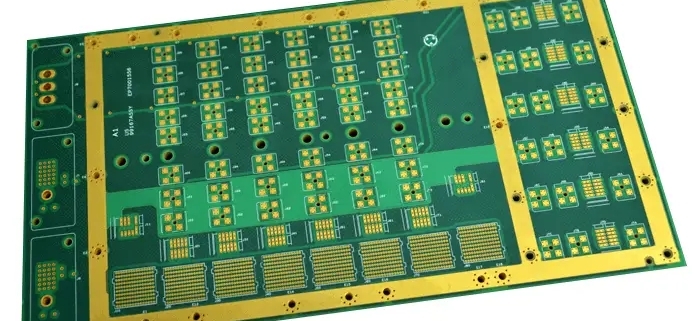
HASL leadfree: HASL leadfree boards are generally multi-layer (4-46 layers) high-precision PCB samples. They have been used by many large domestic communications, computers, medical equipment, aerospace companies and research units. Goldfinger (connecting finger) is the connecting component between the memory module and the memory slot. All signals are transmitted through the gold finger.

Gold fingers are composed of many golden conductive contacts. Because the surface is gold-plated and the conductive contacts are arranged like fingers, they are called “gold fingers”.

Gold fingers are actually covered with a layer of gold on a copper-clad board through a special process, because gold is extremely resistant to oxidation and has strong conductivity.

However, due to the high price of gold, currently more memory is replaced by tin plating. Since the 1990s, tin materials have become popular. Currently, almost all “gold fingers” of motherboards, memory and graphics cards are used. Tin material, only some high-performance server/workstation accessory contact points will continue to use gold plating, which is naturally expensive.

2. Why use gold-plated boards?

As ICs become more integrated, IC pins become more dense. The vertical tin spray process is difficult to flatten the thin pads, which makes SMT mounting difficult; in addition, the shelf life of the tin spray board is very short.

The gold-plated pcb just solves these problems:

1. For the surface mount process, especially for 0603 and 0402 ultra-small surface mounts, the flatness of the solder pad is directly related to the quality of the solder paste printing process and has a decisive impact on the subsequent reflow soldering quality. Therefore, the entire board Gold plating is often seen in high-density and ultra-small surface mount processes.

2. In the trial production stage, due to factors such as component procurement, it is often not possible to solder the board as soon as it comes. Instead, we often have to wait several weeks or even months before using it. The shelf life of gold-plated boards is longer than that of lead. Pewter alloy is many times longer, so everyone is happy to use it.

Besides, the cost of gold-plated PCB in the prototyping stage is almost the same as that of lead-tin alloy plate.

But as the wiring becomes denser and denser, the line width and spacing have reached 3-4MIL.

Therefore, the problem of gold wire short circuit has arisen: as the frequency of the signal becomes higher and higher, the signal transmission in multiple coatings due to the skin effect has a more obvious impact on the signal quality.

The skin effect refers to: high-frequency alternating current, the current will tend to flow concentrated on the surface of the wire. According to calculations, skin depth is related to frequency.

In order to solve the above problems of gold-plated boards, PCBs using immersed gold boards mainly have the following characteristics:

1. Because the crystal structures formed by immersion gold and gold plating are different, immersion gold will be golden yellower than gold plating, and customers will be more satisfied.

2. Immersion gold is easier to weld than gold plating and will not cause poor welding or customer complaints.

3. Since the immersion gold board only has nickel and gold on the pad, the signal transmission in the skin effect is in the copper layer and will not affect the signal.

4. Because immersion gold has a denser crystal structure than gold plating, it is less likely to cause oxidation.

5. Since the immersion gold plate only has nickel gold on the pad, it will not produce gold wires and cause short spots.

6. Since the immersion gold plate only has nickel gold on the pad, the solder resist on the circuit is more firmly bonded with the copper layer.

7. The project will not affect the spacing during compensation.

8. Because the crystal structures formed by immersion gold and gold plating are different, the stress of the immersion gold plate is easier to control. For products with bonding, it is more conducive to bonding processing. At the same time, it is precisely because immersed gold is softer than gold plating that gold fingers made of immersed gold pcb are not wear-resistant.

9. The flatness and service life of the immersed gold plate are as good as those of the gold-plated plate.

For the gold plating process, the tin application effect is greatly reduced, while the tin application effect of immersion gold is better; unless the manufacturer requires binding, most manufacturers now will choose the common immersion gold process In this case, the PCB surface treatment is as follows:

Gold plating (electroplating, immersion gold), silver plating, OSP, HASL leadfree.

These types are mainly for boards such as FR-4 or CEM-3. The paper base material and the surface treatment method of coating with rosin; if the problem of poor tin application (poor tin eating) is excluded, solder paste and other patch manufacturers are excluded. Due to production and material technology reasons.

Here we only talk about PCB issues. There are several reasons:

1. When printing PCB, whether there is oil leakage film surface on the PAN position, which can block the effect of tin application; this can be verified by a tin drift test.

2. Whether the PAN position meets the design requirements, that is, whether the pad design can adequately ensure the support of the parts.

3. Whether the pad is contaminated or not, the results can be obtained by using ion contamination test; the above three points are basically the key aspects to be considered by PCB manufacturers.

Regarding the advantages and disadvantages of several methods of surface treatment, each has its own strengths and weaknesses!

In terms of gold plating, it allows the PCB to be stored for a longer time, and is less affected by the external environmental temperature and humidity (compared to other surface treatments), and can generally be stored for about a year; HASL leadfree surface treatment is second, and OSP is third. A lot of attention should be paid to the storage time of the two surface treatments in the ambient temperature and humidity.

Generally speaking, the surface treatment of immersed silver is a little different, the price is also high, and the storage conditions are more stringent, so it needs to be packaged in sulfur-free paper! And the storage time is about three months! In terms of tin application effects, immersion gold, OSP, HASL leadfree, etc. are actually almost the same. Manufacturers mainly consider cost-effectiveness!

How to determine the step of blind and buried vias? How to judge accurately?

PCB blind buried vias are a common type of vias on PCB boards and are also a widely used process in circuit board manufacturing. But what are the step of blind and buried vias? How to judge accurately?

1. What are PCB blind and buried vias?

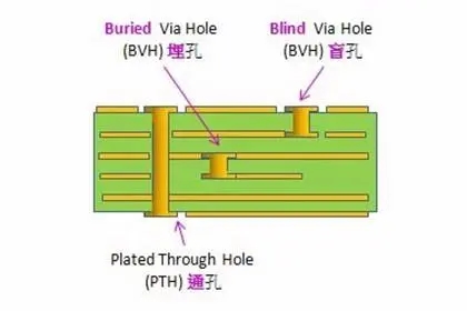
PCB blind buried vias are a type of via that connects the inner layer traces of the PCB to the surface traces. Blind vias and buried vias are two forms of blind and buried vias in PCB. A blind hole is a kind of via that only connects the inner layer and the surface layer. It needs to reserve a certain depth to facilitate the connection. It can be regarded as a kind of via hole of the inner layer pad. The buried via only connects the inner layer traces inside the PCB. It has nothing to do with the PCB surface traces and is usually used for multi-layer PCBs.

2. Definition of step of PCB blind and buried vias

According to the depth of blind holes or buried holes, blind holes or buried holes can be divided into different orders. First order means that one end of the blind hole can be seen, but the other end cannot be seen. The second level refers to a blind hole where neither end can be seen, but the length can be measured with a tool. At the third level, the length of blind holes and buried holes cannot be seen at all, and the length can only be determined by X-ray measurement.

3. How to accurately determine the step of blind and buried holes in PCB

Accurately judging the order of PCB blind and buried holes requires the use of professional instruments and tools for measurement. Commonly used measurement tools include: high-definition microscopes, solder needles, microscopes, and X-ray inspections. Among them, a high-definition microscope is the most basic tool, which can clearly observe blind holes or buried holes. Solder pins can be inserted into blind holes or buried holes to measure their depth. The microscope is suitable for observing blind and buried holes on complex PCB boards, and X-ray inspection is the most intuitive method, which can clearly observe the internal conditions of blind holes or buried holes.

4. The importance of blind and buried vias in PCB

PCB blind and buried vias are closely related to the electrical performance and reliability of PCB. The connection between the inner layer and the surface layer of the PCB is completed through blind holes. The connection quality of the blind hole well reflects the connection quality between the inner layer and the surface layer. If the order of blind holes is incorrect, it will lead to problems such as poor connections or separation of inner and surface traces, thus affecting the electrical performance and reliability of the PCB. Therefore, it is very important to judge the order of PCB blind and buried vias. Professional measurement tools and detection methods should be reasonably selected to ensure the quality of PCB blind and buried vias.

As an important part of PCB, PCB blind and buried vias directly affect the electrical performance and reliability of PCB. Accurately determining the order of blind and buried vias is very important for the PCB manufacturing process. Reasonable selection of professional measurement tools and detection methods can help us accurately judge PCB blind and buried vias and ensure the reliability and electrical performance of PCB.

What is DBC for ceramic copper-clad pcb?

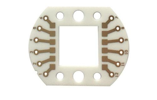
Direct Bonding Copper is a new type of high-performance heat dissipation material. It is a heat dissipation material that organically combines a copper layer with a ceramic substrate. The copper layer can effectively spread and disperse heat, while the ceramic substrate has good Excellent insulation performance and high temperature stability. DBC has the characteristics of good thermal conductivity, high mechanical strength, good impact resistance, and high temperature resistance. It is widely used in electronic packaging, LED lighting, automotive electronics and other industries.

1. The structure of dbc

The main structure of DBC consists of three parts: metal copper layer, ceramic dielectric layer and metal solder. Among them, the metal copper layer is the main body for electrical conduction and heat dissipation. Its good electrical and thermal conductivity ensures the efficient heat dissipation effect of DBC during use. The metal copper layer adopts the chemical copper plating process, which can form a flat copper layer and have small plastic deformation pressure-sensitive properties, which can effectively maintain the stability of the copper layer throughout the product life cycle. The ceramic dielectric layer plays the role of insulation and mechanical support. Because of its lower thermal conductivity compared to the copper layer, it can ensure that it will not have a great impact on the thermal conductivity of the copper layer. Ceramic substrates mainly use alumina, silicon nitride, ceramic composite materials, etc. These ceramic substrates have the characteristics of good high temperature stability, high mechanical strength, and good corrosion resistance. The metal solder is mainly used to bond the copper layer and the ceramic substrate together, effectively providing the strength of the entire DBC product.

2. Preparation of dbc

The preparation of DBC mainly uses modern electrochemical copperization technology, by forming a layer of active metal substances on the surface of the ceramic substrate, so that the copper layer can be deposited while the copper layer is immersed in the active electrolyte. Commonly used ceramic substrate materials include aluminum oxide and silicon nitride. Among them, DAC-A03 is a ceramic substrate used for high-brightness technology, DAC-A05 is a ceramic substrate used for ordinary technology, and DAC-A07 is a ceramic substrate used for high-precision technology. Compared with silicon nitride, the surface of aluminum oxide is smoother, which can greatly improve the bonding degree and heat dissipation efficiency of the copper layer and the dielectric layer. The combination of ceramic substrate and copper layer mainly uses inkjet printing technology and shielding film technology. Both technologies can realize the preparation of customized DBC products. With the continuous improvement of preparation processes and technological advancement, the performance and stability of DBC products will be further improved.

3. Application of dbc

The applications of dbc mainly cover the fields of electronic packaging, LED lighting and automotive electronics. The field of electronic packaging has always been one of the main application fields of DBC. Because electronic equipment generates a large amount of heat during high-power operation, if the heat cannot be dissipated in a timely and effective manner, the equipment may work unstable or even be damaged. DBC has fast heat dissipation speed and excellent thermal conductivity, and has been widely used in the field of electronic packaging. For example, DBC products can be used in semiconductor power modules, high-power LEDs, power electronic devices, etc. In semiconductor power modules, DBC can be used to package IGBTs, MOSFETs, etc., and the long-term stability and reliability of these devices can be ensured through the DBC heat dissipation structure. With the popularity of LED lamps, dbc is increasingly used in the field of LED lighting. LED lamps also generate a large amount of heat during their working process. This heat can be quickly dissipated to the outside world through DBC, ensuring the high brightness and long life of the LED lamps. Automotive electronic equipment also needs to dissipate heat, and the efficient heat dissipation performance of DBC makes it widely used in the field of automotive electronics.

4. Development prospects of dbc

As a new type of heat dissipation material, DBC has extremely high market value and broad application prospects. With the continuous improvement of the performance of dbc products, it will be widely used in electronics, automobiles, aerospace, medical and energy and other fields. In the electronic field, the functions of electronic products are constantly strengthened and intelligent, which also puts forward higher requirements for heat dissipation performance. This requires dbc, as the main product in the field of electronic product heat dissipation, to continuously advance in technology to meet the needs of the market. . Another example is that in the energy field, DBC also has broad application prospects in solar cells, lithium batteries and fuel cells, because these devices also require an efficient heat dissipation system.

As a new type of heat dissipation material, DBC will be widely used in future development due to its superior heat dissipation performance. With the continuous advancement of technology and continued market demand, the application fields of dbc will become more extensive and the market prospects will become brighter.

Is PCB board size marking really that important?

PCB board dimensioning plays a vital role in circuit design and production. It not only ensures the normal operation of the circuit board, but also improves production efficiency and reduces costs. This article will elaborate on the importance of PCB board dimension marking from four aspects, including design specifications, production process, assembly process and reliability testing.

1. Design specifications

PCB board size marking plays an important role in the early stage of circuit design. Reasonable dimensioning can ensure the stability of the connection and installation of the circuit board and external devices, and avoid connection problems and poor signal transmission caused by inappropriate dimensions. In addition, accurate dimensioning can also help designers better control the size and shape of circuit boards during layout to adapt to different application scenarios.

2. Production process

PCB board size marking also has an important impact on the circuit board production process. Reasonable dimensioning can help manufacturers accurately cut circuit boards and avoid waste and repeated processing caused by size discrepancies. In addition, dimensional markings can also guide production personnel in drilling, mounting and other process operations, improving production efficiency and product quality.

3. Assembly process

PCB board size marking also plays a vital role in the circuit board assembly process. Accurate dimensioning can help assemblers install components correctly and avoid problems such as component misalignment and poor welding caused by size discrepancies. In addition, dimensional markings can also guide assembly personnel in welding, testing and other process operations, improving assembly efficiency and product quality.

4. Reliability test

PCB board size marking is also very important for circuit board reliability testing. Reasonable dimensioning can help testers install test equipment accurately and ensure test accuracy and reliability. In addition, dimensional markings can also guide testers to perform operations such as signal testing and temperature testing, improving test efficiency and reliability of results.

From the four aspects of design specifications, production process, assembly process and reliability testing, the importance of PCB board size marking cannot be ignored. Reasonable dimensioning can ensure the normal operation of circuit boards and improve production efficiency and product quality. Therefore, in circuit design and production, we should pay attention to the dimension marking of PCB boards and rationally use marking technology to ensure the stability and reliability of the circuit board.

Enhance product performance! The strong competitive advantage brought by multi-layer PCB lamination process!

As technology continues to advance, the demand for electronic products is also growing. In order to meet consumer requirements for higher performance and smaller size, the multi-layer PCB lamination process has become a key link in the design of modern electronic products.

Multi-layer PCB lamination process can provide higher circuit density. Compared with traditional single-layer circuit boards, multi-layer PCBs can accommodate more electronic components and connection lines, thereby achieving more complex functional integration. This is critical for modern electronics, which often require more functionality and performance in a limited space.

The multi-layer PCB lamination process can also improve the stability and reliability of the circuit. Since the multi-layer PCB adopts a stacked design, the connections between electronic components are closer, reducing interference and loss in signal transmission. In addition, multi-layer PCBs also have better anti-interference performance and can effectively resist external electromagnetic interference and noise. These characteristics make multi-layer PCBs perform well in application fields such as high frequency and high-speed transmission.

In addition, the multi-layer PCB lamination process can also improve the heat dissipation performance of the product. As the power consumption of electronic products increases, heat dissipation issues have become an important factor restricting product performance. The stacking design of multi-layer PCB can effectively improve the heat dissipation effect. Through reasonable thermal conduction design and heat dissipation channels, heat is quickly conducted to the external environment and the normal operating temperature of electronic components is maintained, thereby improving the stability and life of the product.

The multi-layer PCB lamination process can also simplify the product manufacturing process. Compared with using multiple single-layer circuit boards for assembly, multi-layer PCBs can directly weld electronic components to different levels of circuit boards, reducing the use of connecting wires, simplifying the assembly process, and improving production efficiency. This is especially important for large-scale production and fast delivery requirements.

In the electronics industry, mastering the design and manufacturing technology of multi-layer PCB lamination process will bring greater market competitiveness to enterprises. Therefore, we should pay attention to the application and development of multi-layer PCB lamination technology and continuously promote the enhancement of product performance to meet users’ needs for high-quality electronic products.

What is copper-clad? Grid copper coating or solid copper coating?

1. What is copper coating?

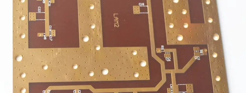
The so-called copper pouring is to use the idle space on the circuit board as the reference plane and then fill it with solid copper. These copper areas are also called copper filling.

The significance of copper coating is to reduce the impedance of the ground wire and improve the anti-interference ability; reduce the voltage drop and improve the power efficiency; connecting to the ground wire can also reduce the loop area.

Also for the purpose of keeping the PCB from deforming as much as possible during welding, most PCB manufacturers will also require PCB designers to fill the open areas of the PCB with copper or grid-like ground wires. If the copper is not handled properly, it will The gain outweighs the loss. Does copper coating have “more pros than cons” or “does more cons than pros”? Everyone knows that at high frequencies, the distributed capacitance of the wiring on the printed circuit board will work. When the length is greater than 1/20 of the corresponding wavelength of the noise frequency, the antenna effect will occur, and the noise will be emitted outward through the wiring. If there is poorly grounded copper in the PCB, the copper becomes a tool for transmitting noise.

Therefore, in high-frequency circuits, do not think that the ground wire is connected to the ground somewhere. This is the “ground wire”. You must drill holes in the wiring with a spacing of less than λ/20, and connect it to the ground. The ground plane of the shelf is “well grounded”. If the copper coating is handled properly, the copper coating not only increases the current, but also plays the dual role of shielding interference.

2. Two forms of copper pouring

There are generally two basic methods of copper pouring, namely large-area copper pouring and grid copper pouring. People often ask whether it is better to pour copper pouring over a large area or with grid copper pouring. It is difficult to generalize.

why? Covering a large area with copper has the dual functions of increasing current and shielding. However, if a large area of copper is covered with wave soldering, the board may warp or even blister. Therefore, when covering a large area with copper, several grooves are usually opened to alleviate blistering of the copper foil.

Pure grid copper coating mainly has a shielding effect, and the effect of increasing current is reduced. From the perspective of heat dissipation, the grid is beneficial (it reduces the heating surface of copper) and plays a certain role in electromagnetic shielding. Especially for circuits such as touch, as shown below: It should be pointed out that the grid is composed of traces in staggered directions. We know that for circuits, the width of the traces has its influence on the operating frequency of the circuit board. The corresponding “electrical length” (can be obtained by dividing the actual size by the digital frequency corresponding to the operating frequency, see relevant books for details).

When the operating frequency is not very high, perhaps the role of the grid lines is not very obvious. Once the electrical length matches the operating frequency, it is very bad. You will find that the circuit cannot work properly at all, and interference is being emitted everywhere. signal of.

The suggestion is to choose based on the working conditions of the designed circuit board, and don’t stick to one thing. Therefore, high-frequency circuits have multi-purpose grids that require high interference resistance, and low-frequency circuits have high-current circuits and other circuits that commonly use complete copper laying.

What are the requirements and precautions for PCB silkscreen design?

1. Silkscreen design requirements

The ratio of character height to character width of silkscreen characters is generally required to be ≥6:1. There are three common font sizes: among them, when the board density is relatively high, 4/25mil characters (No. 1) are commonly used; when the density is normal, 5/ 30mil characters (No. 2); when the board is relatively loose, 6/45mil characters (No. 3) are recommended; usually the base copper thickness of the surface layer also has corresponding requirements for the silk screen width, base copper <1OZ, limit value ≥4mil, optimization value ≥6mil; When the base copper thickness is 1OZ, 5/30mil characters are preferred; when the base copper thickness is 2OZ, 6/45mil characters are preferred.

2. Requirements for adding PCB silkscreen printing

1. Placement: Generally speaking, when placing the silk screen of resistors, capacitors, tubes and other devices, do not use four directions. This will make it very tiring to look at the silkscreen during debugging, maintenance and welding ( How many directions does the board need to turn).

2. Try not to punch the via holes on the silk screen.

3. Do not press the silk screen on high-speed signal lines (such as clock lines, etc.): For high-speed signal lines on the top or bottom layer, because such signal lines can be regarded as microstrip lines.

4. The reading direction of the silk screen should be consistent with the usage direction. The reading direction of the silkscreen should be consistent with the usage direction of the chip. This is mainly to reduce the probability of reverse soldering when welding.

5. The pin number must be clearly marked on the silkscreen.

6. Silkscreen printing for special packages: For special packages such as BGA and QFN, the size of the silk screen must be exactly the same as the size of the chip.

7. Silkscreen printing of the mounting holes: The silkscreen printing of the screws is added near the mounting holes, and the length and total number of screws are also marked to facilitate installation.

3. Precautions for silkscreen design

1. The silkscreen line width on the board should be ≥ 4 mil, and avoid the screen printing line width of components being 0.

2. The distance between the silkscreen and the pads: Do not cover the soldering points on the board with the silkscreen, such as the pads of SMD devices and the through holes of plug-ins. The silkscreen is an insulating material. Once it is applied to the pads, it will cause poor welding; do not cover the test points on the board. , mark points, etc.; it is usually required to maintain a 6mil spacing.

3. The spacing between silkscreens: maintain 6 mil. Overlapping between silkscreens is acceptable. Once the overlap causes unrecognizability, it needs to be adjusted away.

4. Silk screen printing direction: The arrangement of silkscreen strings should follow the principle of from left to right or bottom to top when looking at the screen.

5. Placement of device reference numbers: The device reference numbers should correspond to the devices one-to-one, and the order cannot be reversed or changed. When the device density is relatively high, the method of drawing out labels or symbol markings can be used to place the reference numbers on other parts of the board. Wherever there is space.

6. The component polarity markings and “1” pin markings must be placed correctly and clearly.

7. When introducing annotations or symbol annotations, the added silkscreen and characters should be placed on the silkscreen layer of Board Geometry.

The added board name and version number silkscreen is also placed on the silkscreen layer of Board Geometry.

8. The device tag cannot be placed inside the device body or outside the board frame.

9. When the board density is relatively high and there is really no space to place the tags, you can discuss with the customer not to use the tags, but an assembly drawing is required to facilitate device installation and inspection.

10. When the customer requires copper characters to be written on the top and bottom layers, the line width of the copper characters: HOZ base copper – the character width is more than 8 mil and the height is more than 45 mil; 1OZ base copper – the character width is more than 10 mil and the height is more than 50 mil. At the same time, it is necessary to open the solder mask window so that the copper characters on the produced board will be brighter.

How to design PCB safety spacing?

There are many places where safety distances need to be considered in PCB design. Here, they are temporarily classified into two categories: one is electrical-related safety distances, and the other is non-electrical-related safety distances.

1. Electrical related safety distances

1. Spacing between wires

As far as the processing capabilities of mainstream PCB manufacturers are concerned, the distance between wires must not be less than 4mil. Line spacing is also the distance from line to line and line to pad. From a production perspective, the bigger the better if conditions permit, and 10mil is more common.

2. Pad aperture and pad width

In terms of the processing capabilities of mainstream PCB manufacturers, the pad aperture should not be less than 0.2mm if mechanical drilling is used, and should not be less than 4mil if laser drilling is used. The aperture tolerance varies slightly depending on the board material. It can generally be controlled within 0.05mm, and the pad width must not be less than 0.2mm.

3. The spacing between pads

In terms of the processing capabilities of mainstream PCB manufacturers, the distance between pads must not be less than 0.2mm.

4. The distance between the copper sheet and the edge of the board

The distance between the charged copper sheet and the edge of the PCB board shall not be less than 0.3mm. As shown in the figure above, set this spacing rule on the Design-Rules-Board outline page.

If a large area of copper is laid, there is usually a shrinkage distance from the edge of the board, which is generally set to 20mil. In the PCB design and manufacturing industry, generally, engineers often lay large areas of copper out of mechanical considerations for the finished circuit board, or to avoid curling or electrical short circuits due to copper being exposed on the edge of the board. The block is retracted 20mil relative to the edge of the board instead of spreading the copper all the way to the edge of the board. There are many ways to deal with this copper shrinkage, such as drawing a keepout layer on the edge of the board, and then setting the distance between the copper laying and the keepout. Here is a simple method, which is to set different safety distances for copper-laying objects. For example, the safety distance for the entire board is set to 10mil, and the copper-laying setting is 20mil. This can achieve the effect of shrinking the edge of the board by 20mil, and at the same time Eliminates dead copper that may appear within the device.

2. Non-electrical related safety distances

1. Character width, height and spacing

No changes can be made to the text film during processing, except that the character line widths with D-CODE less than 0.22mm (8.66mil) are thickened to 0.22mm, that is, the character line width L=0.22mm (8.66mil), and the entire character The width = W1.0mm, the height of the entire character H = 1.2mm, and the spacing between characters D = 0.2mm. When the text is smaller than the above standards, it will be blurry when printed.

2. Via-to-via spacing (hole edge to hole edge)

The distance from via (VIA) to via (hole edge to hole edge) is greater than 8mil.

3. Distance from silk screen to solder pad

Screen printing is not allowed to cover the soldering pads. Because if the silk screen covers the soldering pad, tin will not be applied to the silk screen area during tin application, which will affect the mounting of components. Generally, board manufacturers require a spacing of 8mil. If the PCB board area is really limited, a 4mil spacing is barely acceptable. If the silk screen accidentally covers the pad during design, the board manufacturer will automatically remove the silk screen left on the pad during manufacturing to ensure that the pad is tinned.

Of course, the specific situation should be analyzed in detail during design. Sometimes the silk screen is deliberately placed close to the pads, because when the two pads are very close, the silk screen in the middle can effectively prevent the solder connection from short-circuiting during soldering. This situation is another matter.

4. 3D height and horizontal spacing on the mechanical structure

When mounting components on the PCB, it is necessary to consider whether they will conflict with other mechanical structures in the horizontal direction and spatial height. Therefore, when designing, it is necessary to fully consider the compatibility between components, between the finished PCB and the product shell, and the spatial structure, and reserve a safe distance for each target object to ensure that there is no spatial conflict.