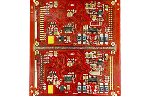
Efficient energy management leads new trends, full analysis of new energy vehicle PCB applications!

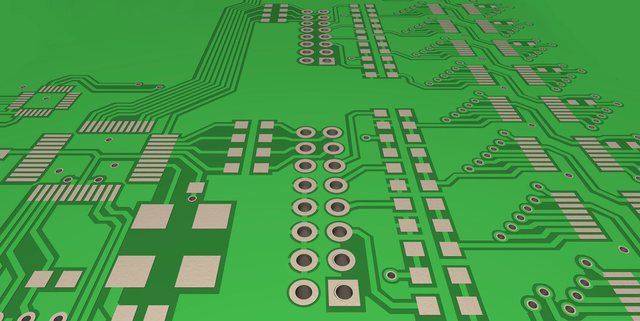
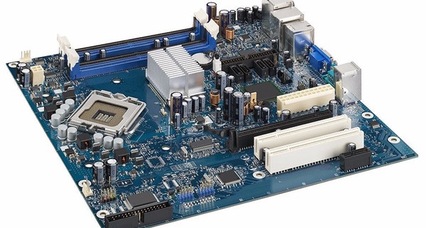
With the increasing global emphasis on environmental protection, new energy vehicles are gradually becoming the mainstream of the automotive industry. In the development of new energy vehicles, efficient energy management is a key link. In new energy vehicles, the application of PCB (Printed Circuit Board) plays a vital role. This article will provide a detailed analysis of new energy vehicle PCB applications from four aspects.

1. Development of new energy vehicle PCB technology
The development of new energy vehicle PCB technology is the basis for achieving efficient energy management. With the promotion of new energy vehicles and the increase in demand, traditional PCB technology can no longer meet the demand for efficient energy management. Therefore, new energy vehicle PCB technology continues to develop to achieve higher energy efficiency and reliability. For example, the application of high-density, multi-layer, and multi-function PCBs can make the wiring of vehicle electronic systems more compact, improve energy conversion efficiency, and provide more possibilities for function expansion.

2. Application of new energy vehicle PCB in battery management system
The battery is one of the core components of new energy vehicles, and the battery management system (BMS) is the key to its effective management. The application of new energy vehicle PCB in BMS can realize battery monitoring, charge and discharge control, temperature management and other functions. Through reasonable design and layout of PCB, the accuracy and stability of BMS can be improved, thereby extending the service life of the battery and improving energy utilization.

3. Application of new energy vehicle PCB in power system
The power system of new energy vehicles is the core component for energy conversion and transmission. In the power system, the application of new energy vehicle PCB can realize functions such as motor drive control, energy conversion between the battery and the motor, and linkage with other systems. Because new energy vehicle PCBs have reliability and stability in special environments such as high temperature and high current, they can improve the efficiency and safety of the power system.

4. Application of new energy vehicle PCB in intelligent systems
Intelligent systems are another important component of new energy vehicles, including car networking, autonomous driving and other functions. The application of new energy vehicle PCB in intelligent systems can realize the collection, processing and transmission of sensor data, and realize intelligent control and optimization of vehicles. Through the high integration and reliability of PCB, it is possible to realize the collaborative work of multiple systems and provide a safer, more efficient and intelligent driving experience.

The application of new energy vehicle PCBs is leading a new trend in efficient energy management. Through the technological development of PCB, the battery management system, power system and intelligent system of new energy vehicles have been greatly improved and optimized. The application of new energy vehicle PCB not only improves energy utilization and vehicle performance, but also enhances vehicle safety and reliability. With the further development of the new energy vehicle market, new energy vehicle PCB technology will continue to innovate and make greater contributions to the efficient energy management of new energy vehicles.

A must-read for engineers! What factors affect PCB stackup design?

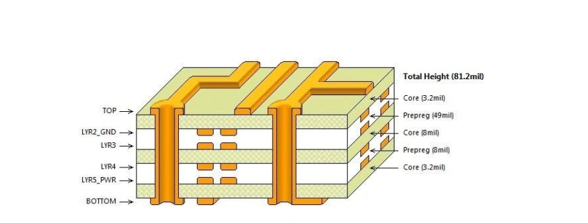
When designing a PCB (printed circuit board), one of the most basic issues to consider is how many wiring layers, ground planes and power planes are needed to achieve the functions required by the circuit. The wiring layers, ground planes and power planes of the printed circuit board The determination of the number of plane layers is related to requirements such as circuit function, signal integrity, EMI, EMC, and manufacturing costs. For most designs, there are many conflicting requirements in factors such as PCB performance requirements, target cost, manufacturing technology, and system complexity. The stack-up design of the PCB is usually determined by a compromise after considering various factors. High-speed digital circuits and whisker circuits usually adopt multi-layer board designs. What factors affect PCB stackup design?

1. Layering

In a multi-layer PCB, it usually contains a signal layer (S), a power (P) plane and a ground (GND) plane. Power planes and ground planes are usually solid planes without separation, and they will provide a good low-impedance current return path for current from adjacent signal traces. The signal layer is mostly located between these power or ground reference plane layers, forming a symmetrical stripline or an asymmetrical stripline. The top and bottom layers of multi-layer PCBs are usually used to place components and a small number of traces. These signal traces must not be too long to reduce direct radiation generated by the traces.

2. Determine the single power supply reference plane (power plane)

The use of decoupling capacitors is an important measure to solve power supply integrity. Decoupling capacitors can only be placed on the top and bottom layers of the PCB. The traces, pads, and vias of the decoupling capacitor will seriously affect the effect of the decoupling capacitor. This requires that the traces connected to the decoupling capacitors should be as short and wide as possible during design, and the wires connected to the vias should also be considered. Keep it as short as possible. For example, in a high-speed digital circuit, you can place decoupling capacitors on the top layer of the PCB, assign layer 2 to the high-speed digital circuit (such as a processor) as the power layer, layer 3 as the signal layer, and layer 4 Set to high-speed digital circuit ground.

In addition, try to ensure that the signal traces driven by the same high-speed digital device use the same power layer as the reference plane, and this power layer is the power supply layer of the high-speed digital device.

3. Determine the multi-power reference plane

The multi-supply reference plane will be divided into several physical areas with different voltages. If there is a signal layer next to the multi-power layer, the signal current on the nearby signal layer will encounter an unideal return path, causing gaps in the return path. For high-speed digital signals, this unreasonable return path design may cause serious problems, so it is required that high-speed digital signal wiring should be kept away from multi-power reference planes.

picture

4. Determine multiple ground reference planes (ground planes)

Multiple ground reference planes (ground layers) can provide a good low-impedance current return path, which can reduce common-mode EMl. Ground planes and power planes should be tightly coupled, and signal layers should be tightly coupled to adjacent reference planes. This can be achieved by reducing the thickness of the media between layers.

5. Reasonable design of wiring combinations

The two layers spanned by a signal path are called a “routing combination.” The best routing combination design avoids return current flow from one reference plane to another, but flows from one point (plane) of a reference plane to another point (plane). In order to complete complex wiring, interlayer conversion of wiring is inevitable. When converting between signal layers, it is necessary to ensure that the return current can flow smoothly from one reference plane to another. In a design, it makes sense to treat adjacent layers as a routing group. If a signal path needs to span multiple layers, it is usually not a reasonable design to use it as a routing group, because a path through multiple layers is not clear for return current. Although the ground bounce can be reduced by placing decoupling capacitors near the vias or reducing the dielectric thickness between the reference planes, it is not a good design.

6. Set the wiring direction

On the same signal layer, the direction of most wiring should be consistent and orthogonal to the wiring direction of adjacent signal layers. For example, you can set the wiring direction of one signal layer to the “Y-axis” direction, and set the wiring direction of another adjacent signal layer to the “X-axis” direction.

7. Adopt an even-numbered layer structure

From the designed PCB stackup, it can be found that the classic stackup design is almost all even-numbered layers, not odd-numbered layers. This emergency is caused by a variety of factors, as shown below.

It can be understood from the manufacturing process of printed circuit boards that all conductive layers in the circuit board are stored on the core layer. The material of the core layer is generally a double-sided cladding board. When the core layer is fully utilized, the conductive layer of the printed circuit board The number is even.

Even-layer printed circuit boards have cost advantages. Due to the lack of one layer of dielectric and copper coating, the cost of raw materials for odd-numbered printed circuit boards is slightly lower than the cost of even-numbered printed circuit boards. However, because odd-numbered layer printed circuit boards require a non-standard laminated core layer bonding process based on the core layer structure process, the processing cost of odd-numbered layer printed circuit boards is significantly higher than that of even-numbered layer printed circuit boards. Compared with the ordinary core structure, adding copper cladding outside the core structure will lead to a decrease in production efficiency and a prolongation of the production cycle. The outer core layer also requires additional processing before lamination and bonding, which increases the risk of scratches and incorrect etching of the outer layer. The added outer layer treatment will significantly increase manufacturing costs.

When the inner and outer layers of the printed circuit board are cooled after the multi-layer circuit bonding process, different lamination tensions will cause the printed circuit board to bend to varying degrees. And as the thickness of the board increases, the risk of bending of a composite printed circuit board with two different structures increases. Odd-numbered circuit boards are prone to bending, while even-numbered layers of printed circuit boards can prevent the circuit board from bending.

During design, if there are an odd number of layers, you can use the following method to increase the number of layers.

If you design a printed circuit board with an even number of power layers and an odd number of signal layers, you can use the method of adding signal layers. The added signal layer will not lead to an increase in cost, but can shorten the processing time and improve the quality of the printed circuit board.

If you design a printed circuit board with an odd number of power layers and an even number of signal layers, you can use the method of adding power layers. Another simple method is to add a ground layer in the middle of the stack without changing other settings, that is, first lay out the odd-numbered printed circuit board layers, and then copy a ground layer in the middle.

In microwave circuits and mixed media (media with different dielectric constants) circuits, a blank signal layer can be added near the center of the PCB stackup to minimize stackup imbalance.

8. Cost considerations

In terms of manufacturing cost, with the same PCB area, the cost of multi-layer circuit boards is definitely higher than single-layer and double-layer circuit boards, and the more layers, the higher the cost. However, when considering factors such as circuit function and circuit board miniaturization, and ensuring signal integrity, EMl, EMC and other performance indicators, multi-layer circuit boards should be used as much as possible. Comprehensive evaluation shows that the cost difference between multi-layer circuit boards and single- and double-layer circuit boards is not much higher than expected.

What impact does the stencil have on the processing quality of SMT patches?

1. How to make stencil

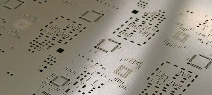
At present, the main methods of making stencil are: chemical etching, laser cutting, and electroform.

Chemical etching has large errors and is not environmentally friendly; the data production accuracy is high and the influence of objective factors is small; the trapezoidal opening is conducive to demoulding; precision cutting can be done; the price is moderate; the hole wall is smooth, especially suitable for ultra-fine pitch steel mesh production method, and the price is high .

At present, most SMT chip processing factories use laser stencil, which is cost-effective and of good quality.

2. Stencil material

Generally, the steel mesh is made of stainless steel, which has high printing accuracy and long service life.

3. Stencil thickness

The thickness and size of the stencil directly determine the amount of tin on the pad, directly affecting whether problems such as virtual soldering and tin connection will occur.

Usually there are both components with a spacing of 1.27mm or more and components with a narrow spacing on a PCB. Components with a spacing of 1.27mm or more require a stainless steel plate 0.2mm thick, and components with a narrow spacing require a stainless steel plate 0.15-0.10mm thick. The thickness of the stainless steel plate can be determined based on the condition of most components on the PCB, and then the amount of solder paste leakage can be adjusted by expanding or reducing the size of the pad opening of individual components.

If there is a large difference in the amount of solder paste required for components on the same PCB, the template at the narrow-pitch components can be partially thinned, but the processing cost of the thinning process is higher. Therefore, a compromise method can be adopted. The thickness of the stainless steel plate can be an intermediate value. For example: some components on the same PCB require 0.20mm thickness, and other components require 0.15-0.12mm thickness. In this case, the thickness of the stainless steel plate can be 0.18 mm.

4. Stencil  size

The opening size can be 1:1 for general components. For large Chip components and PLCC that require a large amount of solder paste, the opening area should be expanded by 10%. For devices such as QFP with pin spacing of 0.5mm and 0.65mm, the opening area should be reduced by 10%.

5. Stencil  shape

Appropriate opening shape can improve the placement effect. For example: when the size of the chip component is smaller than 1005 and 0603, due to the small distance between the two pads, the solder paste on the pads at both ends can easily flow to the bottom of the component during placement. Adhesion, bridges and solder beads at the bottom of components can easily occur after reflow soldering. Therefore, when processing the template, the inside of the opening of a pair of rectangular pads (Figure 1) can be modified into a sharp angle or an arc shape (Figure, Chip component opening shape) to reduce the amount of solder paste at the bottom of the component, which can improve the component placement The solder paste on the bottom is sticking.

6. Stencil performance requirements

The frame is not deformable. The tension should be average and high, preferably 30 N/㎜? or above. The metal should be flat. The metal plate thickness error is less than ±10%. The opening should be aligned with the PCB (high accuracy). The opening section of the steel plate should be vertical, and the protruding part in the middle should not be greater than 15% of the thickness of the metal plate.

The dimensional accuracy of the opening of the steel plate for SMT patch processing must be within the tolerance ±0.01㎜ and shall not exceed 0.02㎜. The thickness and opening size of the stencil directly affect the amount of solder paste printed. During production, parameters such as the thickness and opening size of the stencil need to be confirmed to ensure the quality of solder paste printing.

What does the thermal expansion coefficient of PCB board mean? How was it measured?

The thermal expansion coefficient of the PCB board refers to the change in the length of the material per unit length under unit temperature change when the temperature of the material changes. Simply put, it is the proportion of length change caused by temperature changes when a material is heated or cooled.

The thermal expansion coefficient is a material physical property parameter used to describe the behavior of materials during thermal expansion and contraction. It can affect the dimensional accuracy and performance stability of materials. Especially for electronic devices, accurate understanding and control of the thermal expansion coefficient is crucial to ensure product quality and reliability.

The coefficient of thermal expansion is usually expressed in ppm/°C (parts per million per degree Celsius). For example, assuming a material has a thermal expansion coefficient of 20 ppm/°C, the length of the material will increase by 0.002% of the original length for every 1°C increase in temperature.

PCB board is a common electronic component substrate and is widely used in the fields of electronics and communications. Electronic devices generate heat during operation, and thermal expansion and contraction are very common. Therefore, it is very important to select the appropriate PCB board material and accurately measure its thermal expansion coefficient.

There are many methods to measure the thermal expansion coefficient of PCB boards. Two common measurement methods will be introduced below.

1. Expanded cantilever beam method

The expansion cantilever beam method is an indirect method of measuring the thermal expansion coefficient and is often used for small sample testing of PCB board materials. The principle is to calculate the thermal expansion coefficient by measuring the deflection of the material under temperature changes.

The specific experimental steps are as follows:

(1) Prepare a thin slice sample of appropriate size and fix it on the support beam to form a cantilever.
(2) Place the cantilever in a constant temperature environment and record the baseline deflection.
(3) Gradually heat or cool the cantilever and record the deflection at different temperatures.
(4) Use Hooks’ law to calculate the thermal expansion coefficient based on the deflection changes at different temperatures.

The advantage of this method is that the testing process is relatively simple and the equipment requirements are low. However, measurement accuracy may be limited because of the small sample size.

2. Thermal expansion coefficient meter method

The thermal expansion coefficient meter method is a method of directly measuring the thermal expansion coefficient and is suitable for testing large-size PCB board materials. This method calculates the thermal expansion coefficient by accurately measuring the linear expansion of materials at different temperatures.

The specific experimental steps are as follows:

(1) Prepare PCB board samples of suitable size.
(2) Fix the sample in the thermal expansion coefficient meter and establish the zero position of the measuring instrument.
(3) Adjust the temperature and record the sample length at different temperatures.
(4) Calculate the thermal expansion coefficient based on the recorded length changes.

The advantage of this method is that the test accuracy is relatively high and the thermal expansion coefficient of large-size samples can be accurately measured. However, the instruments and equipment are relatively expensive, and the testing process requires operators to have a certain technical level.

In addition to the above common measurement methods, there are other methods such as cantilever beam method, thermal difference method and expansion volume method. Each method has its applicable scope and advantages, and the choice should be based on actual needs.

To sum up, the thermal expansion coefficient of PCB board refers to the proportion of material length change per unit length under unit temperature change. Accurate measurement of thermal expansion coefficient is very important to ensure the quality and reliability of electronic devices. Common measurement methods include the expansion cantilever beam method and the thermal expansion coefficient meter method. Each method has its advantages and disadvantages and needs to be selected according to the actual situation.

Automotive PCB board process requirements, how to ensure driving safety and stability?

Automotive PCB board technology is an indispensable key link in modern automobile manufacturing. It is directly related to the driving safety and stability of the car. This article will elaborate on the automotive PCB board process requirements from four aspects and discuss how to ensure driving safety and stability.

1. Design requirements
Design is the basis of automotive PCB board technology and is related to the stability and reliability of the entire electronic system. The wiring of automobile PCB boards should be reasonable to avoid interference and electromagnetic compatibility issues to ensure the stability of circuit transmission. The impact of environmental factors such as temperature and humidity on the PCB board should also be considered in the design, and appropriate protection measures should be selected, such as moisture-proof, dust-proof, etc., to improve the durability of the PCB board. In addition, the repairability of the PCB board needs to be considered to facilitate later maintenance and upgrades to ensure driving safety.

2. Material selection
The correct selection of PCB board materials is crucial to ensuring driving safety and stability. Materials with good high-temperature properties should be selected to adapt to the high-temperature requirements of the automotive working environment. The materials should also have lower dielectric loss and better signal transmission performance to improve signal stability. For automotive PCB boards that require fire resistance, materials with better flame retardant properties should be selected to ensure that the fire source can be extinguished in time in the event of an accident. Taking these factors into consideration, selecting appropriate materials can improve the performance and reliability of automotive PCB boards.

3. Manufacturing process
The manufacturing process is a key link in ensuring the quality of automotive PCB boards. A good printed circuit board (PCB) manufacturing process can ensure the accuracy and stability of the circuit and improve the overall quality of the board. A reasonable surface treatment process can improve the connection stability between the PCB board and components, reduce contact resistance, and improve the circuit quality. transmission efficiency. The assembly process of PCB is also very important to ensure welding quality and reliability and prevent circuit failures caused by poor welding. Through good manufacturing technology, the quality and stability of automobile PCB boards can be ensured and driving safety can be improved.

4. Quality control
Automotive PCB board process requirements also require strict quality control measures. Develop and implement strict standards and specifications to ensure that the production of PCB boards meets the specified requirements. Necessary quality inspections and tests are performed during the production process to ensure that every link meets the requirements to reduce the production of defective products. Establish a complete quality traceability system to track and analyze possible quality problems and take corrective measures in a timely manner. Through quality control, PCB board quality problems can be avoided to the greatest extent and the safety and stability of driving can be improved.

Automotive PCB board process requirements play a vital role in ensuring driving safety and stability. Only when all aspects meet the standard requirements can the quality and stability of the automotive PCB board be guaranteed. The automobile manufacturing industry should attach great importance to these requirements in practice, strive to improve the driving safety and stability of automobiles, and provide users with a better driving experience.

What is a car PCB board? What is the difference from a regular circuit board?

Automobile pcb board, that is, printed circuit board for automobiles. As the carrier of on-board electronic equipment, it plays a vital role in the operation of the car. However, what is so special about it that makes it stand out from ordinary circuit boards?

1. Concept and composition of automobile pcb board
Automotive PCB boards are important components used to install electronic components and provide connection paths for various electronic devices and systems in vehicles. It usually consists of a substrate, conductive paths, circuit components, etc. The substrate materials of automotive PCB boards mainly use high-temperature, heat-resistant, moisture-resistant, and corrosion-resistant materials to cope with various challenges in the automotive environment. Conductive paths are usually printed on the substrate. These copper conductive paths are called printed circuits, which connect circuit components and form paths for current flow. Circuit components, such as resistors, capacitors, inductors, diodes, transistors, etc., are key components of automotive circuit boards. They are inseparable from controlling automotive power systems, environmental sensing, navigation and other functions.

2. Application fields of automotive circuit boards
The complexity of modern automobiles far exceeds the mechanical equipment visible to the naked eye of drivers in the past, and automobile PCB boards are used in many fields. For example, the power control system is used to control the entire power system of the car, including the engine, transmission, brakes, etc.; the on-board information system is used to realize navigation, communication, entertainment and other functions; the safety control system involves here including the body stability system, Airbag control, etc.; environment perception systems, such as reversing radar, raindrop detection, etc. Each function requires targeted design and production of automotive PCB boards, which have strict requirements on the performance of automotive PCB boards.

3. Functions and characteristics of automobile pcb boards
The biggest function of the automobile PCB board is undoubtedly to provide connections for electronic components and form a current path for various electronic devices and systems in the automobile. Its performance parameters mainly include high temperature resistance, vibration resistance, humidity resistance, corrosion resistance and other properties. Because of the complexity of the automotive working environment, automotive PCB boards need to cope with a variety of harsh environments such as high temperature, humidity, vibration and impact. Therefore, in terms of material selection and design, there are very high requirements for weather resistance and strength, which are much higher than those of ordinary PCB boards. The circuit board is more powerful.

4. The difference between automobile pcb board and ordinary circuit board
Compared with ordinary circuit boards, automotive PCB boards have significant differences in many properties. The main differences are greater weather resistance and strength. There are higher requirements for the design and production of automobile PCB boards, which need to meet the harsh working environment of automobiles and their complex and changing functional requirements. Automotive PCB boards also have higher vibration resistance and waterproof performance, and pay more attention to environmental protection, because for outdoor equipment such as cars, vibration resistance, waterproofness and environmental protection are particularly important. Automotive PCB boards may be more complex and sophisticated than ordinary circuit boards, because various precise control and adjustment functions in the automotive system need to be implemented by electronic circuits, which requires the circuits to be determined to be more sophisticated and complex.
High temperature resistance, vibration resistance, humidity resistance, corrosion resistance and other properties enable automotive PCB boards to work stably in complex and harsh automotive environments. Compared with ordinary circuit boards, automotive PCB boards are more sophisticated and complex, and meet various functional requirements at the same time, showing their superiority and complexity. Understanding these is of great significance for us to better understand automotive PCB boards and their important role in automotive electronic systems.

PCB wiring analog circuit and digital circuit part

Wiring features:

1. The placement direction of components determines the direction of wiring.

2. The wiring directions of adjacent layers are different. The wiring main body of the surface layer and the welding layer of the two panels is 90?3. The wiring direction of the rectangular circuit board is longitudinal. Horizontal wiring can easily cause congestion or even failure to wire.

4. Try to ensure the wiring space. When this is not possible, use specific components for wiring, and try to avoid connecting holes under the components.

Because when the circuit board fails, it is impossible to visually see the status of the connection holes under the components and whether they are short-circuited with other wiring or component pins.

Analog circuit part and digital circuit part

Including wiring, the analog circuit part and the digital circuit part must be kept above 5mm to ensure that there is no signal interference with each other.

When a symbol is used to represent a ground wire in a circuit diagram, the circuit board designer needs to analyze the circuit diagram and set a certain area. Power cords and ground wires were originally designed. For two-panel and four-layer boards, the wiring composition is completely different. Because the power supply and ground wires are set on the inner layer, attention is mainly focused on them. Just focus on the layout of the signal lines. For beginners, it is recommended to start with the design of four-layer boards. The wiring of power lines and ground wires has a great impact on electricity and noise, so they must be designed carefully.

Take two panels as an example:

○The power cord and ground wire are designed on the same layer, and the effect is very poor

○The ground wire is on the surface and the power wire is on the welding layer. General design

○The ground wire is on the surface, the power wire is on the welding layer, and is wired in copper foil, which has a better anti-clutter effect. Because of the uncontrollability of CAD design, the design takes longer than simple wiring. Pay attention to ensure a small wiring width to ensure that no disconnection or flow obstruction occurs.

To put it simply: the power cord and ground wire are equivalent to the aorta and veins of the human body. You can also simply think of water pipes. The wider the line width, the greater the current flow and faster heat dissipation. The narrower the line width, the greater the resistance under the same voltage, the smaller the current flow that can pass, and the slower the heat dissipation.

Surface welding surface

For power lines and ground wires, large-scale copper foil wiring is used.

Precautions for wiring power lines and ground wires on two-layer circuit boards

Normally, the power wire is routed on the welding surface, the ground wire is routed on the surface, and copper foil is used to wire a wide area, and then some more capacitance is added between the power wire and the ground wire, and there is basically no problem. But if electromagnetic interference is involved, the problem is different. When it exceeds 8MHz, problems of this kind may occur. When it exceeds 25MHz, it will become quite unstable. At this time, it is necessary to surround the important components with ground copper foil, and also design the ground copper foil on the soldering surface.

Crystal oscillator wiring

In order to resist interference, the components should be surrounded by ground copper foil as much as possible. What is not shown in the picture is that ground copper foil can also be laid under the crystal oscillator on the soldering layer, and then the surface and the soldering surface are connected with connection holes. Enhance anti-interference ability.

The use of thermal resistive pads

When power lines and ground wires are routed using large pieces of copper foil, they should be designed using heat-resistant pads as much as possible. This is because if the component pad is directly connected to a large piece of copper foil, the heat will dissipate quickly during welding, and the temperature of the melted solder will not be enough, resulting in poor welding or virtual soldering.

Thermal resistive pad

Power supply for analog circuits

The output part should be close to the power supply. In order to not be affected by the output part, the high-sensitivity input part must be kept at a certain distance from the output part.

Analog circuit diagram Schematic diagram of the separation of digital circuit and analog circuit parts Power input part

DC power supply: When power is provided from the outside, it must first pass through the electrolytic capacitor and then be provided to the internal circuit. The wiring method is usually as follows.

The two-layer panel provides power to the internal circuit not through point A, but through point B. The multi-layer panel also introduces power to the inner layer after passing point B.

Nine rules for high-speed PCB signal routing

In high-speed PCB design, critical high-speed signal lines such as clocks need to be shielded. If there is no shielding or only part of it is shielded, it will cause EMI leakage. It is recommended that shielded wires be drilled and grounded every 1000mil.

Rule 2

High-speed signal routing closed-loop rules

As the density of PCB boards becomes higher and higher, many PCB LAYOUT engineers are more likely to make a mistake during the routing process, that is, high-speed signal networks such as clock signals produce closed-loop results when routing multi-layer PCBs. , such a closed-loop result will produce a loop antenna, increasing the radiation intensity of EMI.

Rule three

Open-loop routing rules for high-speed signals

Rule 2 mentions that the closed loop of high-speed signals will cause EMI radiation, but the open loop will also cause EMI radiation. In high-speed signal networks such as clock signals, once an open loop occurs during multi-layer PCB routing, a linear antenna will be generated, increasing the radiation intensity of EMI.

Rule 4

Characteristic impedance continuity rules of high-speed signals

For high-speed signals, the characteristic impedance must be continuous when switching between layers, otherwise the EMI radiation will be increased. In other words, the width of wiring on the same layer must be continuous, and the impedance of wiring on different layers must be continuous.

Rule five

Wiring direction rules for high-speed PCB design

The wiring between two adjacent layers must follow the principle of vertical wiring, otherwise it will cause crosstalk between lines and increase EMI radiation. In short, adjacent wiring layers follow the horizontal and vertical wiring directions, and vertical wiring can suppress crosstalk between lines.

Rule 6

Topology rules in high-speed PCB design

In high-speed PCB design, the control of the circuit board’s characteristic impedance and the design of the topology under multiple loads directly determine the success or failure of the product. The diagram shows a daisy chain topology, which is generally beneficial when operating at a few Mhz. Star symmetry of the backend is recommended in high-speed PCB designs.

Rule 7

Resonance rules for trace length

Check whether the length of the signal line and the frequency of the signal constitute resonance. That is, when the wiring length is an integer multiple of 1/4 of the signal wavelength, the wiring will resonate, and the resonance will radiate electromagnetic waves and cause interference.

Rule 8

Return path rules

All high-speed signals must have good return paths. Ensure that the return path of high-speed signals such as clocks is as small as possible. Otherwise, radiation will be increased, and the size of the radiation is proportional to the area enclosed by the signal path and the return path.

Rule 9

Device decoupling capacitor placement rules

The placement of the decoupling capacitor is very important. Unreasonable placement will not achieve the decoupling effect at all. The principle is: be close to the pins of the power supply, and the area surrounded by the power supply traces and ground wires of the capacitor is small.

FPC flexible circuit board bending skills help you create tough electronic products!

In the manufacturing process of electronic products, FPC flexible circuit boards play a vital role. Its softness and foldability make the design of electronic products more flexible while also improving the durability of the product. However, bending FPC circuit boards is not a simple task and requires some skills and precautions.

1. Durability of fpc flexible circuit board

FPC flexible circuit boards have outstanding durability, which is mainly reflected in the following aspects.

Excellent flexibility: FPC flexible circuit boards use flexible base materials, so they can work under deformation conditions such as bending, twisting and folding. Compared with rigid circuit boards, fpc flexible circuit boards can adapt to more installation environments, thus improving the durability of the product.

High shock resistance: Due to the flexibility of the FPC flexible circuit board, when subjected to mechanical shock or vibration, compared with the rigid circuit board, the FPC circuit board can better resist and buffer the impact force, thereby reducing the risk of the circuit board risk of damage.

Reliable connectivity: FPC flexible circuit board uses pressure-sensitive adhesive connection method, which has good conductivity and reliability. Even under long-term use and frequent bending, the connection life on the circuit board is guaranteed, thereby increasing the service life of electronic products.

2. Bending skills help create tough electronic products

When using FPC flexible circuit boards for bending processing, the following are some practical tips to help create tough and durable electronic products.

Reasonable design of the bending area: When designing the bending area of the FPC flexible circuit board, the curvature and bending radius of the circuit board need to be fully considered. Reasonable bending area design can reduce stress concentration and reduce the risk of circuit board damage.

Choose the appropriate bending process: For the bending process of FPC flexible circuit boards, there are many methods to choose from, such as manual bending, mechanical bending, etc. According to different product requirements and circuit board characteristics, choosing the appropriate bending process can minimize circuit board damage.

Control the bending force and speed: During the bending process of FPC flexible circuit boards, you need to pay attention to controlling the bending force and speed to avoid excessive force and fast speed causing circuit board rupture. Appropriate force and speed can ensure the integrity and stability of the circuit board.

FPC flexible circuit boards show excellent durability in electronic products, can adapt to various installation environments and resist impact, and extend the service life of the product. At the same time, reasonable bending design and control of the bending process and speed help create tough and durable electronic products. It is believed that FPC flexible circuit boards will play an increasingly important role in the future design and manufacturing of electronic products.

turnkey PCB assembly

What are the uses of printed circuit boards?

Printed Circuit Board (PCB) is a plate-like infrastructure used to connect and support electronic components. In modern electronic equipment, PCB has become the mainstream technology for circuit connection and support of electronic components.

1. Electronic equipment manufacturing
Printed circuit boards are an important part of electronic equipment and are widely used in electronic products, including mobile phones, laptops, desktop computers, digital cameras, televisions and other electronic equipment. Printed circuit boards connect electronic components through current to realize various circuit functions. In the manufacturing process of electronic equipment, printed circuit boards play a key role, and their quality has a great impact on the service life and performance of electronic equipment.
2. Industrial automation
In the field of industrial automation, printed circuit boards are widely used in industrial controllers, sensors and various automation control equipment. Printed circuit boards realize various automated control tasks by combining various circuits to transmit control signals and collect various data.
3. Aerospace
In the aerospace field, printed circuit boards are widely used in high-end equipment such as navigation systems, communication systems, and radar systems. Printed circuit boards must not only meet many technical requirements such as high-speed data transmission and high-precision measurement, but also must meet stringent conditions such as ambient temperature, humidity, and radiation.
4. Medical equipment
Printed circuit boards play an increasingly important role in medical equipment, including medical imaging equipment, life monitoring instruments, etc. As an important part of electronic equipment, printed circuit boards need to meet stringent technical requirements such as safety, accuracy, and stability.
Printed circuit boards are widely used in modern electronic equipment manufacturing, industrial automation, aerospace, medical equipment and other fields. They are an important part of modern high-tech industries. Their technical level is crucial to the development of all walks of life. important role.